What's In The Bag


Cable Ties, Adhesive Mounting Tape, and Wire Taps
Technical Information
- Housing Dimensions: 1.42" square, 0.315" thick
- Weight packaged: 0.244 Lb
- Wire type: #20 600V rated
- Contact Closure Info: This is not a current carrying contact, it can only be used to close circuit between its two wires.
- Weight installed with wires: 0.202 Lb
- Wire lengths: Power feed, 24" Sense wire yellow 36". Wire to opener 36".
- Package includes: 3 8" tie wraps, 6 4" tie wraps, 2 wire clips, adhesive tape, instructions.
How It Works
AS7G will close contacts or "short" the same 2 points that become shorted inside your garage-remote-control-transmitter whenever you press the activation button. The AS7G closes the circuit to activate your remote, for 1-second each time you activate the AS7G by whatever circuit it is triggered by on the vehicle. The best way to trigger the AS7G would be the high beam, or brake light (best to set up AS7G as 2-pulse) or a horn or the turn signal cancel button on many BMW bikes only.The 2 orange wires from the AS7G must be soldered inside your remote for this to happen.
If you want your AS7 to be commanded by 1 single long pulse (more than 1.2 second), rider presses the high beam button (for example) and holds for 1.2 second at which time the LED starts blinking fast orange color, and then release the high beam button. The LED turns green while it is "pressing" your remote's button. This will activate the garage remote.
If you programmed your new AS7 to be a dual quick pulse version, you press the high beam button twice quickly (less than 1 second between press or click-ons). The LED blinks fast during the process. The LED turns green while it is "pressing" your remote's button.
For BMW Motorcycles with analog or digital CAN-BUS the above sequences for single or dual pulse can be activated by the turn signal cancel button, instead of the high beam wire.
Another options is instead of the handlebar high beam or turn signal cancel buttons (BMW), the AS7G can sense voltage going to the tail light brake bulb. This permits 2 "touch-taps" on the hand brake or brake foot pedal just a light press to activate brake light twice quickly. In some cases, the installation of the AS7G is simpler with easier to access wire at the rear.
Identifying or locating the trigger wire
For all vehicles:
We can trigger from the high beam wire, or the brake bulb wire or any wire that gets 12Volts when an existing button (for some other use) is activated. The best starting point is the vehicle electrical diagrams however in most cases it is not available. The best method is to use a clothespin or other needle-like sharp rod to put on the end of your volt meter probe. Pushing the needle into the vinyl jacket of most wires will not damage the wire. Determine the most likely location of the wanted wire. For example if using a high beam trigger this would be right behind that control button, or on a connector leading from that control button. Alternate, maybe easier location can be near the high beam bulb instead. Now simply poke into the intended wire with the needle probe and trigger the button on and off (In this case high beam lights) continuously while looking for a reaction or 12V at the volt meter. Always have the black probe (ground -12V) connected to chassis or battery negative terminal. Once the trigger wire is identified, mark it with tape or marker. Knowing the colors of this wire can also permit finding the same wire easier at a more crowded wire bunch such as near main vehicle fuse box or computer, then simply verifying it once again.
For BMW CAN-BUS Motorcycles 2004/2005/2006 and later:
Turn ON the ignition and search for the 12V+ wire that turns OFF, behind the turn signal cancel button while the button is pressed, or activated. Notice the wire colors. Then locate same wire colors and confirm it at the chassis computer. The connection at the chassis computer is usually easier with more work space and a thicker wire at that point.
For BMW R and K models aprox 1994-2004/2005:
With the ignition OFF, search for the wire that shorts to ground, behind the turn signal cancel button while the button is pressed, or activated. Notice the wire colors. Then locate same wire colors and confirm it at the turn signal module. The connection at the turn signal module is usually easier with more work space and a thicker wire at that point. For this test, the VOM Volt meter will be set to Ohms or impedance to find a "short" or closed circuit.
For other BMW Motorcycles:
Early F models did not use a BMW electronic turn signal cancel and are considered non-BMW. Later F and G models, exact info not known. However if electronic, chances are it will be CAN-BUS otherwise mechanical and this would be determined upon close inspection.
Installation
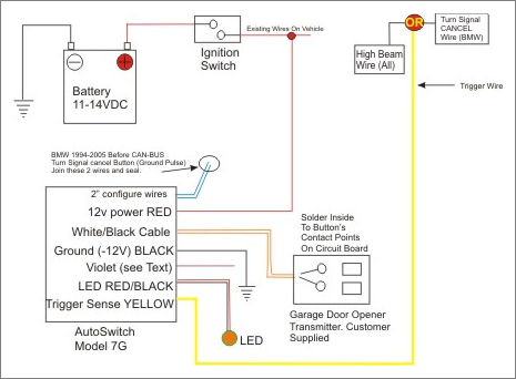
The Autoswitch is easy to install. Connect the 2 orange wires to your garage-door-remote transmitter or have us do it for you. Tap the RED into any ignition-swtiched 'ON' wire for power, YELLOW wire to the high beam bulb or turn signal cancel wire. Add connection to ground, and neatly tuck the Autoswitch and wires out of the way in any convenient location. And without building a bracket, drilling any holes, or modifying your dash, you’re done! The garage transmitter should be placed away from large metal that can block a long range signal to your garage door receiver.
Your garage door control transmitter normally activates when you push a button on it. The 2 orange wires on AS7G must be soldered inside on the same points that your pushbutton contacts together. A small soldering pencil, solder and a VOM (Volt-Ohm-Meter) is required. The circuit board is accessed by opening up the transmitter housing. This can be performed for you in our tech lab for a nominal cost of $22 post paid, if you send us the remote.
Go ahead and look at the detailed instruction sheets but don't be spooked by the amount of text! The above paragraphs are really what it's all about if you are a knowledgeable tech or shade-tree mechanic.
Operational System Details
Sensing sequence: The AS7G upon power up of the circuit (red wire and black wire) checks the trigger wire (yellow wire) for 1 second to to detect 12V+. If yellow wire gets powered up within 1 second AS7G determines this to be a BMW CAN-BUS circuit while ignoring digital info on the line. If it does NOT get powered up then AS7G determines it to be a standard vehicle which will later apply +12V pulse there for activation. A pre-CAN-BUS BMW bike (aprox 1994-2004) will also not apply any voltage to the yellow wire. The yellow wire on this older BMW bike sees a floating open line, and this requires installer to connect the 2 short blue wires on AS7G together.
User Program Change
Program change 1 or 2 pulses activation: The AS7G normally is packaged with the processor programmed for 1 pulse. This means trigger is activated for over 1.2 second then LED flashes and trigger is released during the fast flash of the LED. LED then turns green for 1 second while garage remote is activated. The AS7G is easy to program so it uses 2-quick-pulses for activation. The 2 quick pulses have to be less than 1 second apart and again, during LED flashing.
To Change Program: Simply hold the trigger (yellow wire) to +12V Or Ground/open line, depending on your vehicle set up, for 40 seconds solid. After the 40 seconds the LED starts flashing quickly now at this time pulse the trigger wire (remove the 12V+ OR ground) a few times, and LED will go green for 1 second to indicate success. These directions are on the instruction sheet however saying to use the trigger button already connected to the yellow wire.
LED Indicator Light Extra Information
The LED shines steady RED when the AS7G has the 2 orange wires "open". The LED shines steady GREEN for 1 second during the time the 2 orange wires are "closed circuit" and activating your remote. The short violet wire is also powered up 1 second +12V, for optional uses or certain Garage Remotes.
This LED has a lens on top. The housing is a 5mm diameter, 7mm tall. There is a 1mm long flange at the bottom that's 6mm diameter. The wire underneath needs approximately 20mm before a full bend can be made. This stiffness is only due to all the layers of protective heat shrink tubing. By modifying this area the bottom of the LED wire section can be set up much smaller.
The LED is a bi-color. Red or Green. It changes color by getting the voltage on the feed wire reversed by the processor. When the LED is quickly pulsed the color appears orange to the eye. The wire is 6 to 7 feet long. It should never be cut or altered due to the danger of damaging the processor chip. If the wires are shorted when the Autoswitch is powered up, the processor chip will be instantly ruined.